|

The L1 Ultradyne receiver was not the only one designed by R.E.
Lacault, he designed several others: the Ultradyne L2 and L3,
the LR4 and the R.E.L.9. Were each an improvement over the
previous one. But what he called his masterpiece was the R.E.29
receiver, the last of the series.
The ingenious circuit of Monsieur Lacault -
Part II
In the mid-twenties a new type of tube with four electrodes, the
Tetrode, was introduced. The addition of a grid, the so-called "screen
grid", which isolated the input grid (or "control grid") from
the plate (or anode) allowed to obtain a more stable amplifier
circuit and a higher gain.
The tetrode was invented by Dr. Walter Schotty (the inventor of
the famous Diode) in Germany, the patent application was applied
in 1916 with No. 300,617 (a U.S. Patent, No 1,537,708 was
released to him in 1925) but reached the "popularity", in
particular in the United States, at the end of the twenties
through the development and production of General Electric. The
new grid inserted between the control one and the plate,
polarized by a positive voltage lower than the anode and acting
as an electrostatic shield, lowered the capacitance between them.
This condition led to the elimination of any spurious
oscillations and then to a more stable amplifier and with a
higher amplification factor , no neutralization was necessary (which
was usually done with the triode) in the RF and IF amplifiers
stages, and allowed to reach higher frequencies.
Probably the idea of using tetrodes in his receivers came to
Lacaut at the end of 1928 in fact the RE-29, he designed and
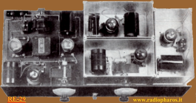
that was introduced in 1929, was using three of them. The
intermediate frequency amplifier stages of this receiver had
three tetrodes working stably and with high gain at 120
kilohertz. These stages, being of grat amplification, had a
metallic cylindrical screen on tubes (see figure) and were
screened each other (as was also the local oscillator) to
prevent spurious couplings and then autoscillation. The
shielding system was very original because it consisted of
aluminum boxes with sliding walls (see photo). The modulator
tube (it is at left in the photo) was not shielded by one of
this boxes being of low amplification and having already a
metallic shield slipped over it. The antenna and oscillator,
designed to cover the Medium Wave band, were wounded on supports
with plugs so as to be interchangeable in order to receive, with
appropriate coils, other frequency bands. I will not dwell more
in the description of the RE-29 because what is most interesting
it's the mixer or modulator tube. Lacault used his mixing
circuit or Modulation System he invented.

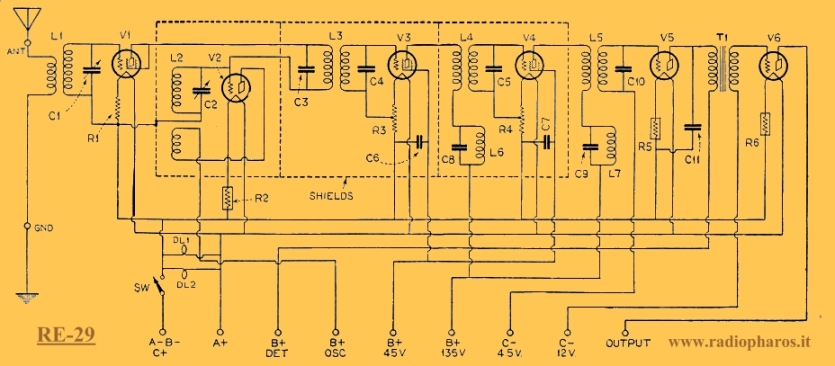
No radio frequency amplifier stage was present, the antenna
signal passed from the RF filter directly to the grid of the
mixer. Neverthless, he obtained a receiver with excellent
sensitivity, this was his main goal. Since the modulator tube
was used in a triode fashion (having the plate connected
directly to the screen grid), gave a lower impedance to the
plate and this, he claimed, improved mixing. Here, as in the
other receivers designed by Lacault, the plate of the mixer was
not powered by any DC voltage but from the AC voltage produced
in the local oscillator tuned circuit L2C2 (which could reach
several tens of volts) through the primary of the first IF
transformer (L3C3). A negative bias of 2.7 volts, which
was derived from the voltage drop in resistor R1, was applied to
the control grid. In addition to what had already been stated in
the original description of the Ultradyne L1 receiver (see part
I) as far as the Modulator Tube, the designer was describing
that of the RE-29 as follows:
"The voltage (that
of the oscillator)
is alternately positive and negative: the positive loops of this
voltage are modulated by the signal impressed on the grid of the
first tube (mixer).
The modulator (or first detector) established a high detecting (mixing)
efficiency because the impedance of the load on the tube is high
for the detected frequency (IF)
and low for the signal frequency (RF).
The fixed- tune circuit L3 (primary) C3, is parallel-tuned for
the intermediate frequency, and his impedance or resistance is
extremaky high. The condition for low impedance at the signal
frequency (RF)
would not be met were not the signal frequency always much
different for both the intermediate frequency and the oscillator
frequency. Currents of the signal frequency pass through C3 with
practically no impedance. Likewise they pass through either C2
or the secondary of the L2. If the higher frequency of the
frequency setting of the oscillator is used, the signal
frequency is lower, and hence passes through the coil. If
the lower oscillator frequency is used, the signal frequency is
high and therefore passes through the condenser C2. This is a
band-pass filter action."
N.B.
What added between brackets in yellow are my notes.
The last part of the above is perhaps not very clear, but one
must take into account that the RE-29 superheterodyne had 2
separate tuning controls, that of the RF signal and that of the
local oscillator, then you could have the oscillator frequency
higher or lower than the (unchanged) RF signal, wich always gave
a 120kHz IF, example:
(LO) 1120 kHz - (IF) 120 kHz = 1000kHz (RF)
(LO) 0880 kHz + (IF) 120 kHz = 1000kHz (RF)
R.E. Lacault began the description of this receiver underlining
its sensitivity;
"When I placed my hand near the antenna binding post of the
RE-29 that I had just completed there was enough field strength
to produce signals from every local station in New York City,
proving that the new circuit was amazingly sensitive."
Lacault dedicated his failing strength, but always with a
brilliant mind, to complete the construction and description of
this receiver, he died a few days later.
Notes:
1-
The Strobodyne circuit is often erroneously credited to Lacault,
actually it was invented in 1927 by Lucien Chrétien in France.
The Strobodyne superheterodyne mixer circuit was very
interesting, it was exploiting a triode as a converter in an
autoscillating switching circuit. Chrétien compared it with the
strobe effect, hence the name Strobodyne. Later he modified it
using two separate tubes, this circuit resembled in part to the
Ultradyne.
References:
1- Radio News - Various 1929 issues

PART I
www.radiopharos.it
Copyright© 2012--2021 All rights
reserved
Tutti i diritti riservati
1st issue - January 2012

|
|
