RF Mixers
www.radiopharos.it
IN SEARCH OF THE IDEAL RF MIXER
Vincent Italia
|
|
||||||
|
The passion and interest for the receivers, primarily of super heterodyne type, took me over the years to focus my attention in the mixer stage which is undoubtedly the most critical. The design of the mixer was, and is, a pain and a challenge among the various designers. The supremacy is being fought, in particular, with ever higher IP3 or TOIP values! In the mid / late eighties I tried different types of mixers, a few unpublished, with results that I would say interesting, I resumed the "research", although occasionally, in 2003. Below is described one of those mixers.
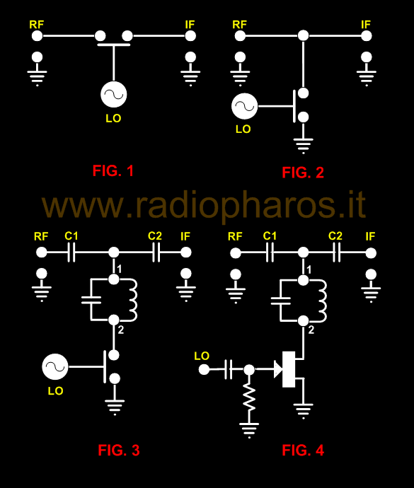
SEM - AN INEDITED PASSIVE FET MIXER WITH
|
||||||
|
The switching mixer is usually of passive type and therefore without DC voltage
(if not for the Bias) and consequently gives an insertion loss. What I am about
to describe is of the same type, but provides a (positive) conversion gain and therefore
has a novel configuration.
The operation of this unusual circuit is the following:
The RF signal is sent, via the capacitor C1, to the primary of
the first IF transformer that is an integral part of the mixer.
This signal is in series with the L/C primary that does not
oppose any resistance or impedance (but opposes it to the
frequency of the IF), then transits undisturbed and appears at
pin 2 which is connected to the drain of the FET whose acting as
a switch opening and closing at the rhythm of the local
oscillator frequency. The resulting IF signal that we find in
pin 1 of the transformer, which being in parallel, is filtered
by the same transformer. The extraordinary thing is that, with
this configuration, the signal undergoes an “amplification"! This
is due to the mixing mechanism that in the primary of the
transformer produces a sort of magnification of the IF signal at
resonance, so we have a passive mixer with voltage gain! Simple, is
not it?
The amplification that we can obtain ranges from a minimum of 3dB to more than
10dB (!). It is linked to the Q of the tuned
circuit of the IF transformer. By also using the secondary we
get more selectivity but less gain due to the insertion loss of
the filter. This can be remedied by coupling the primary to the
secondary with a capacitor. While not a balanced circuit, the
rejection of the local oscillator in the RF and IF ports is
quite good and is mainly due to the inner workings of the FET.
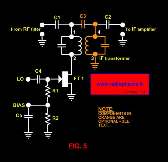
In Table A are shown the results obtained from a prototype built
with a JFET N-channel type BF246A and a 467 kHz IF transformer
(Geloso type 671). Note the good value of the 1 dB compression
point. The circuit diagram is shown in Figure 5. The RF filter
can produce a further "amplification" due to the turns ratio of the
antenna transformer, this gain is however limited by the low
value of the C1 capacitor which serves, also, to "isolate" the RF tuned
circuit from that of the IF transformer. The latter must be
readjusted on the value of the original frequency because the
capacity of the RF circuit tends to move it to a lower one.
Nothing prevents us to interpose an RF amplifier stage or a
buffer (source follower). Also the value of rejection of the
local oscillator in antenna is improved thanks to the filtering
and the step-down of the antenna circuit. The BIAS voltage is
required to operate the JFET as a switch. This mixer, like most
of the switching mixers, has a tendency to mix with harmonics of
the local oscillator; accordingly a good RF filter is strictly
necessary. It will be apparent to those skilled in the art of RF
mixers design that the "switch" can also be of another
kind,
even a tube!
TABLE
A TEST FREQUENCY: 10 MHz IF FREQUENCY: 467kHz BIAS: -5.30 Volts LO LEVEL: <1Volt RMS GAIN: 12dB
GAIN:
>10dB
1 dB IN. COMPRESSION: LO/RF REJECTION: >23dB
LO/RF REJECTION: >30dB LO/IF REJECTION: >23dB LO/IF REJECTION: 37dBw/IF secondary connected
|
||||||
|
N.B. The contents (circuits, drawings, etc.) of this page belong to the writer and owner of this website. You can use them for your pleasure and homebrew purposes. It is forbidden to copy them and use them for commercial business without the owner’s consent.
Copyright©
2013--2021 All rights reserved
|
||||||