|
LACAULT
I wanted to start this series of articles on RF Mixers, that I hope to publish on a regular basis, with an article dedicated to the Ultradyne circuit dated 1924 that might be called, in my modest opinion, the precursor of modern mixers.
The ingenious
circuit of Monsieur Lacault -
Part I
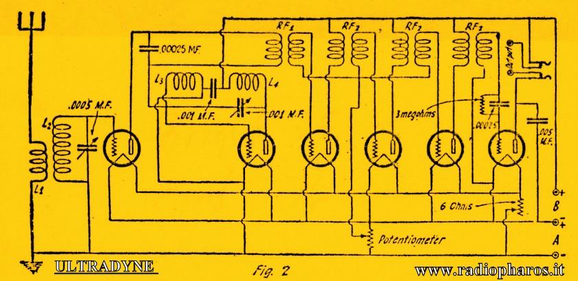
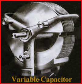
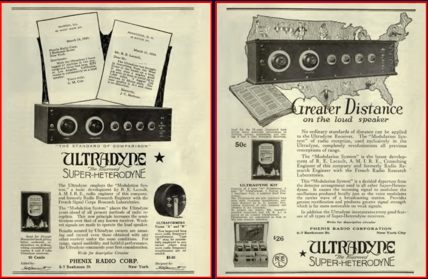
Mister Robert Emile Lacault, born in Paris in 1897*, was an engineer of the Radio Research Laboratories of the French Army Signal Corps. In the early twenties he moved to the United States (New York City) where he became an associate editor, with Mr. Hugo Gernsback, of the famous magazine Radio News. In this magazine (and others) he published several technical articles, but it's in the 1924 February issue of Radio News where appeared his most famous and interesting article. He described a super heterodyne receiver, with a new type of mixer, called Ultradyne to distinguish it from the various circuits of other inventors and named always with the final word "dyne" (see Infradyne, Neutrodyne, Strobodyne, Tropadyne, etc..). In France, some years before and precisely in August 4, 1917, Meur Lucien Lévy applied for a patent of an invention where he exposed, what appeared to be, the basics of the super heterodyne circuit, it became a Patent on August 19, 1919 with No. 493,660. On the 1st October 1918 he asked for a second patent application in which he described an improved version of his invention. (Patent No. 506,297 issued May 27, 1920). At that time U.S. Army Major Edwin H. Armstrong was in France and that's where he presented his version of the super heterodyne to the Patent Office (December 1918). In the United States Armstrong filed his invention in February 1919 (patent issued in June 8, 1920 with N° 1,342,885). From this arose the controversy between the two of who was the inventor of the super heterodyne. In 1929, after a long legal case, the Court of Appeals for the District of Columbia gave reason to Lévy. The U.S. Patent Office issued to him a patent in November 5, 1929 under N ° 1,734,038. In the meantime, namely in February of 1924, Lacault deposited his invention to the United States Office of Patents and became a patent almost six years later, on December 24, 1929, under N ° 1,740,946. This long time to patent his invention was necessary because of various disputes with Armstrong. In reality the Lacault circuit was a super heterodyne but with a completely new and original type of mixer circuit. The first “home" super heterodyne radio receiver designed by Lacault was released in 1924 by the Phenix Radio Corporation of New York, where he was a consultant. This first model was called Ultradyne (shortly later Ultradyne L-1) and sold in 1924, only in kit (without cabinet) because of patent disputes, other models followed more or less improved. Later Lacault dissociated himself from Radio News and became Chief Engineer of the same Phenix where he developed, among other things, a low loss variable capacitor that, thanks to the plates of the stator with a particular cut, was giving to the receivers a very linear frequency response. Robert E. Lacault died in New York City, March 12, 1929. The original Lacault mixer circuit used two tubes, namely two triodes. He called his mixing circuit "Modulation System" and the mixer tube, then called Detector, "Modulator Tube." Lacault was comparing his system to a Transmitting station and a Receiving station. The Modulator is the "microphone" where the "voice" (the RF signals received by the antenna) modulates the "Transmitter" (the local oscillator) and the "Receiver" is the intermediate frequency amplifier! The Modulation System, as explained by Lacault, exploits the characteristic of the tube to change its internal resistance (Ri), between the filament (the triode with cathode came later) and the plate of the triode, whose value depends on the intensity of the received signal on the grid and to its polarity. The plate of the Modulator Tube is not powered by the +B voltage but by the AC local oscillator (LO) voltage drawn from the grid (through the IF transformer coil) of the oscillator tube! When the instantaneous polarity of the radio frequency (RF) signal, present on the grid (without Bias) of the Modulator, is positive, the tube has the lowest internal resistance (conduction) and thus more current flows, it is practically infinite (cut-off) when the polarity is negative therefore the current flow is minimal. If the RF signal has a high level, change in resistance is extended and the triode acts as a ON/OFF "switch" almost shorting to ground (when ON) the oscillator signal through the filament. In case of weak signals, the variation is less extensive but the mixing always occurs. This alternate changing state (at the rate of the RF signal frequency), coinciding with that of the LO, produces the difference or the sum between the RF and the LO and then the intermediate frequency (IF) is created. As you will recall the modulator has the plate that is "powered" (no DC voltage) by the local oscillator AC signal and is therefore "active" only in the positive half-wave. Apparently, though Lacault has not specified in the description of his invention, the mixing seems to occur in the primary of the first IF transformer where the two signals (the switched RF and the LO signal) "meet" and not in the Modulator Tube (1). A simple and ingenious circuit (2) of almost ninety years ago! Chapeau à Monsieur Lacault! I think it would be fair that the Ultradyne circuit appear in the various radio books along with the other tube mixers circuits.
Mixing with variable resistance, a mixer as a ON/OFF switch? All
this brings us to today technology with the switching mixer and
in particular to the passive FET mixer used, in fact, as a
variable resistor. But here it’s the LO signal that causes a
change in its internal resistance and having, the oscillator, a
steady and high level the FET always functions as an ON/OFF
switch that commutes to ground, or interrupts (depends on
design), the RF signal. As you can see there is nothing new
under the sun!
Notes:
1- With
reference to Figures 3, 5, 6 and 8 of the original Patent: in
this case mixing seems to occur in the headset coil. As evident these
circuits can be considered Direct Conversion receivers.
Revision B *In a ship boarding document (taken from an archive), from France to United States and vice versa, in the name of Robert E. Lacault and his wife Alice, appears, as a year of birth for both, 1897. In another (more recent) document, turns out to be 1894. It is evident that there is an inconsistency. 1894 seems to be the most truthful.
References: 1- http://antiqueradios.com/superhet/#f1
2-
R.E. Lacault – Radio Receiving System – Patent N°
1.740.946 - 3- Radio News – February 1924 – The Ultradyne Receiver – by R.E. Lacault 4- Radio Broadcast – Various issues 5- http://www.sparkbench.com/homebrew/Superhet/ultradyne.html
I found an interesting demonstration of the Ultradyne L-1 receiver performance on You Tube:
http://www.youtube.com/watch?hl=en&v=O4lNOmoOp1g&gl=US
www.radiopharos.it
Copyright© 2011--2021 All rights
reserved
1st Issue - August 2011
|