|
L. CHRETIEN
In the twenties, several inventors were unleashed in trying to obtain more sensitive and performing superheterodyne circuits. The Strobodyne invented in 1927 by L.Chrétien is, as the Ultradyne, one of the most original.
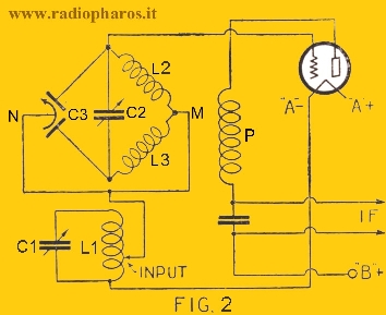
The STROBODYNE mixer circuit
Notes: 1- In reality, the Strobodyne is based on the same principle of the Ultradyne, namely it uses the tube as an automatic switch to interrupt rhythmically the RF signal or that of the OL, in order to create the IF. Perhaps L. Chrétien was inspired by the work of R.E. Lacault and tried to perfect the idea, in that time they knew each other and had worked together.
2-
The
Strobodyne
mixing circuit
is often
erroneously
credited
to
Lacault.
He
sponsored
and
introduced
it to
the United
States
in mid-1927
by
translating from the
French
the
Chrétien's
technical
articles
and
published
them in the
Radio
News magazine,
also by building
a receiver
with
this system adapting
it to
American
components.
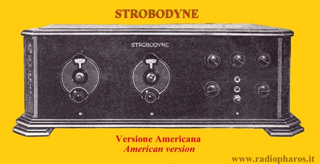
In the USA
there
was also
a
production of
radio
receivers,
cured by
Lacault,
that were called
Strobodyne.
In France there were several radios manufacturers who adopted
the Strobodyne system, as Bouchet et Aubignat, C.A.R.A.C. and
O.R.A.
References:
www.radiopharos.it
Copyright© 2012--2021 All rights
reserved
1st Issue - April 2012
|