|
|
The passion and interest for the receivers, primarily of super heterodyne type,
took me over the years to focus my attention in the mixer stage which is
undoubtedly the most critical. The design of the mixer was, and is, a pain and a
challenge among the various designers. The supremacy is being fought, in
particular, with ever higher IP3 or TOIP values! In the mid / late eighties I tried
different types of mixers, a few unpublished, with results that I would say
interesting, I resumed the "research", although occasionally, in 2003. Below is
described one of those mixers.
DOUBLE TRIODE PASSIVE RF MIXER

Vincent Italia
|
|
|
|
|
Ever since it was invented, the superheterodyne radio
teased the imagination of radio designers in trying to get more and more
efficient mixers and with better performance. Soon it was realized that the
mixing action not only produced the trigonometric product of the RF signal with
that of the local oscillator, and therefore their sum or difference, but also
the generation of spurious originated mainly from strong signals in antenna.
In the sixties, a talented protagonist in the world of RF mixer design was
undoubtedly William K. Squires, chief designer and vice president of
Squires-Sanders, Inc. As is known to those who, like me, for many years now
hang out in the world of Radio, he designed a switching balanced mixer with an
electrostatic beam deflection tube that was used successfully in the SS-1R and
SS-IBS receivers of the aforementioned company. In 1967 he designed a two FETs
balanced passive mixer with excellent characteristics with regard to the
intermodulation and noise figure (Ref.1 and 2), but perhaps little is known, to
most people, that he also designed a mixer with a dual triode, with the same
principle as the one with the two FET. This mixer was used in the AN/URR-58
receiver for the U.S. Coast Guard. The characteristics of this receiver were and
are exceptional (Ref. 3), and this aroused in me curiosity and interest.
Unfortunately I have not managed yet to get hold of a circuit diagram of the
receiver but thanks to a draft of the principle of the mixer circuit, which
appeared on Ham Radio 1973 (Fig.1 and Ref.4), I was able to build an
experimental version , this in the mid-eighties.
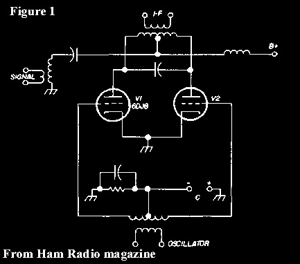
The mixer employs a dual triode tube type 6DJ8 (ECC88
equivalent) in a singular balanced configuration. The RF signal
is sent to the center tap of the primary of the first
intermediate frequency transformer where the two out of phase signals
of the local oscillator are, theoretically, canceled. The tube is
biased for a Class C operation, this allows it to act as a
switch and then to commutate alternately to ground the RF signal
through the two cathodes, according to the polarity of the RF
voltage generated by the local oscillator. The IF signal is picked
up in the intermediate frequency transformer secondary. In the
AN/URR-58 this circuit was preceded by a tube RF amplifier
stage.
The schematic that I have reconstructed is that of Figure 2
where it can be noted that the sinusoidal signal of the LO is
sent to the two grids in Push-Pull, via a broadband unbalanced /
balanced transformer. The fixed negative Bias voltage is sent to the
grids through VR1 which serves to balance it. The circuit can be
simplified by eliminating VR1 and a resistor, as well as the
four capacitors (see Fig.1). In my case these components were
necessary because I used, at first, a Push-Pull tube oscillator.
Then I added the broadband transformer, useful not only to have
a balanced LO signal with any oscillator (or test generator),
but also to raise its level. The tests and assessment
measurements brought the results that appear in Table A and as
you can see they are excellent! To be noted that in the original
Squires version the oscillator has a square waveform and therefore the
compression point would be even better!
FIGURE 2
|
Ca |
500
pF/250V. |
|
R1 |
470
kΩ/1/2W |
|
Cb |
0.01
μF/250V. |
|
R2 |
470
kΩ/1/2W |
|
C1 |
820
pF |
|
T1 |
IF
TRANSFORMER W/CENTER
TAP PRIMARY |
|
C2 |
820
pF |
|
T2 |
UNBAL./BAL. WIDEBAND
TRANSFORMER |
|
C3 |
0.01
μF
|
|
V1 |
6DJ8/ECC88 or 6922/E88CC |
|
C4 |
0.01
μF |
|
VR1 |
100
kΩ
LINEAR
POTENTIOMETER |
|
C5 |
0.01
μF |
|
Z1 |
2.5
mH RFC |
|
R |
4.7
kΩ/2W |
|
|
www.radiopharos.it |
PARTS
LIST
|
TEST FREQUENCY
|
7 MHZ |
|
INTERMEDIATE FREQUENCY
|
500kHz |
|
BIAS (NEGATIVE)
|
-12Volts D.C. |
|
LO LEVEL
|
4 Volts RMS (each grid) |
|
INSERTION LOSS*
|
4dB (0dB with 0V. Bias/
Grounded) |
|
1dB COMPRESSION POINT
(INPUT-50 Ω)
|
> +23dBm*** |
|
MINIMUM DISCERNIBLE SIGNAL
M.D.S. /50 Ω **(SSB 2kHz B.W.)
|
Better than
-119dBm |
|
LO/RF REJECTION (Pin 2 of T1) |
>25dB |
|
LO/IF REJECTION (Pin 5 of T1) |
>75dB |
|
RF(500kHz)/IF REJECTION (Pin 5 of T1) |
35dB
(45dB with 0V. Bias/
Grounded) |
|
* Between pins 2 and 5 of
T1
** RF tuned circuit with
x10
voltage gain factor
***
Measurement limited by available generator
|
www.radiopharos.it |
TABLE A
Subsequently I made a simple but substantial change to the
circuit, the removal of the B voltage! The FET, as we know, can
function as a mixer without any power supply, but here it is a
thermionic tube! It is true that in the past tube diodes have
been used as mixers (some of a special kind like the double
diodes RD12 or LG12) but in the concerned circuit we are dealing
with a double triode!
In fact we have to do with a tube that functions as a switch
(more specifically as a variable resistor) and not as an
amplifier. In help are the Bias and the RF local oscillator
voltages. The modified version appears in Figure 3 where it can
be seen that the intermediate tap of the IF transformer primary
(and therefore the tube plates) is brought to ground via the antenna
circuit.
FIGURE 3
By varying the Bias voltage change the
performance of the mixer, this makes us understand that the tube
continues to work as a triode (double). It can be groped to
explain the operation of this unusual mixer, and with these
particular working conditions, in the following way: the plate being connected to the ground,
is at the same polarity as the cathode. The electrons, which always have a negative charge,
are expelled from the cathode, which is also of negative polarity. As usual, the grid
functions as a flow regulator of the electrons, and hence to their
journey toward the plate (or anode), which being negatively charged
are attracted by the grid because in this case has a fixed positive
bias, and leaves them to pass on their way toward the anode
that, however, tends to repel them being of the same negative
polarity. When the grid becomes negative (negative half-wave of the oscillator voltage),
it is a barrier for the electrons that cannot overcome it in order to reach the plate
(which in any case would reject them, being of the same polarity). Electrons flow is forced back to the cathode.
Things are reversed again when the grid is back with positive polarity. The
fact is that this rhythmic change of state varies the anode
current of the tube and thus also its internal resistance,
therefore the ends of the primary IF transformer are alternately
connected to ground by the two triodes. It is obvious that a
circuit of this type can only produce an insertion loss but
being a high impedance circuit the raising of the RF signal,
thanks to the antenna filter step-up, amply compensates for the loss and
results in an excellent sensitivity!
The sensitivity in the modified circuit is better than in the
original one, probably the absence of the anode voltage, and
thus a very low current in the plates, significantly decreased
the noise. With a good voltage gain factor of the radiofrequency
filter an RF amplifier stage is almost superfluous. Differences
in performance between the two circuits, the one with B power
and that without are evident by comparing the results in Table A
and Table B.
|
TEST FREQUENCY
|
7 MHZ |
|
INTERMEDIATE FREQUENCY
|
500kHz |
|
BIAS (POSITIVE) |
+12Volts
D.C. |
|
LO LEVEL
|
4 Volts RMS (each grid) |
|
INSERTION LOSS*
|
4dB (6db with 0V. Bias/
Grounded) |
|
1dB COMPRESSION POINT
(INPUT-50 Ω)
|
+23dBm |
|
MINIMUM DISCERNIBLE SIGNAL
M.D.S. /50 Ω **(SSB 2kHz B.W.)
|
Better than
-124dBm |
|
LO/RF REJECTION (Pin 2 of T1) |
>40dB |
|
LO/IF REJECTION (Pin 5 of T1) |
>90dB |
|
RF(500kHz)/IF REJECTION (Pin 5 of T1) |
45dB
|
|
* Between pins 2 and 5 of T1
** RF tuned circuit with
x10
voltage gain factor
|
www.radiopharos.it |
TABLE B
Therefore we have an excellent mixer, with a dual-triode tube,
that has been modified in a passive mixer with superior
performance. But....if we also remove the fixed positive grid voltage,
what happens? It continues to work but there is an increase in
the insertion loss of 2dB which then takes from 4 to about 6 dB
total. The RF local oscillator voltage is sufficient to operate
the tube!
What? If we remove also the voltage to the filaments?! No, this
is not possible!!
Unless we find another system to heat the filament and then emit
electrons ......
NOTE:
See Addendum:
http://www.radiopharos.one/addendum-mixer.htm
References:
1-
William K. Squires - W2PUL
Mixer
circuit employing linear resistive elements
Patent N° 3,383,601.
2-
Ulrich L. Rohde DJ2LR
a - Communications receivers for the year 2000
Ham Radio magazine - November 1981
b - Performance capability of active mixers
Ham Radio magazine - March 1982
3-
www.radiopharos.it
Squires-Sanders, Inc. - AN/URR-58 Receiver
4- Ray
Moore -
K1DBR
Designing
communications receivers for good strong signals performance
Ham Radio magazine - February
1973
5-
www.radiopharos.it
SEM - An
inedited passive FET Mixer with conversion gain
6-
www.radiopharos.it
Conversion gain in passive mixer
|
|
|